Wednesday, 20 June 2012

CDMA (Code Division Multiple Access) (Documented by Raghav Kalia and Rahul Madhotra, Appreciable work)


Code division multiple access (CDMA) is a channel access method which refers to any of several protocols used in second-generation (2G) and third-generation (3G) wireless communications. As the term implies, CDMA is a form of multiplexing, which allows numerous signals to occupy a single transmission channel, optimizing the use of available bandwidth. The technology is used in ultra-high-frequency (UHF) cellular telephone systems in the 800-MHz and 1.9-GHz bands.
CDMA employs analog-to-digital conversion (ADC) in combination with spread spectrum technology. Audio input is first digitized into binary elements. The frequency of the transmitted signal is then made to vary according to a defined pattern (code), so it can be intercepted only by a receiver whose frequency response is programmed with the same code, so it follows exactly along with the transmitter frequency. There are trillions of possible a frequency-sequencing code, which enhances privacy and makes cloning difficult.


The CDMA channel is nominally 1.23 MHz wide. CDMA networks use a scheme called soft handoff, which minimizes signal breakup as a handset passes from one cell to another. The combination of digital and spread-spectrum modes supports several times as many signals per unit bandwidth as analog modes. CDMA is compatible with other cellular technologies; this allows for nationwide roaming.

An analogy to the problem of multiple access is a room (channel) in which people wish to talk to each other simultaneously. To avoid confusion, people could take turns speaking (time division), speak at different pitches (frequency division), or speak in different languages (code division). CDMA is analogous to the last example where people speaking the same language can understand each other, but other languages are perceived as noise and rejected. Similarly, in radio CDMA, each group of users is given a shared code. Many codes occupy the same channel, but only users associated with a particular code can communicate.

Steps in CDMA MODULATION:


Each user in a CDMA system uses a different code to modulate their signal. Choosing the codes used to modulate the signal is very important in the performance of CDMA systems. The best performance will occur when there is good separation between the signal of a desired user and the signals of other users. The separation of the signals is made by correlating the received signal with the locally generated code of the desired user. If the signal matches the desired user's code then the correlation function will be high and the system can extract that signal. If the desired user's code has nothing in common with the signal the correlation should be as close to zero as possible (thus eliminating the signal); this is referred to as cross correlation. If the code is correlated with the signal at any time offset other than zero, the correlation should be as close to zero as possible. This is referred to as auto-correlation and is used to reject multi-path interference.


Spread-spectrum characteristics of CDMA

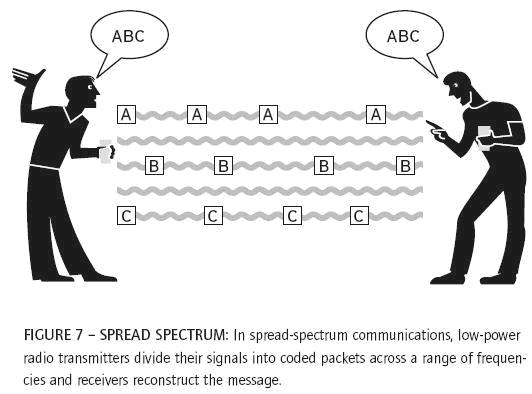
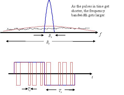
Most modulation schemes try to minimize the bandwidth of this signal since bandwidth is a limited resource. However, spread spectrum techniques use a transmission bandwidth that is several orders of magnitude greater than the minimum required signal bandwidth. One of the initial reasons for doing this was military applications including guidance and communication systems. These systems were designed using spread spectrum because of its security and resistance to jamming. Asynchronous CDMA has some level of privacy built in because the signal is spread using a pseudo-random code; this code makes the spread spectrum signals appear random or have noise-like properties. A receiver cannot demodulate this transmission without knowledge of the pseudo-random sequence used to encode the data. CDMA is also resistant to jamming. A jamming signal only has a finite amount of power available to jam the signal. The jammer can either spread its energy over the entire bandwidth of the signal or jam only part of the entire signal.
  

Frequency reuse is the ability to reuse the same radio channel frequency at other cell sites within a cellular system. In the FDMA and TDMA systems frequency planning is an important consideration. The frequencies used in different cells must be planned carefully to ensure signals from different cells do not interfere with each other. In a CDMA system, the same frequency can be used in every cell, because channelization is done using the pseudo-random codes. Reusing the same frequency in every cell eliminates the need for frequency planning in a CDMA system; however, planning of the different pseudo-random sequences must be done to ensure that the received signal from one cell does not correlate with the signal from a nearby cell.
Since adjacent cells use the same frequencies, CDMA systems have the ability to perform soft hand offs. Soft hand offs allow the mobile telephone to communicate simultaneously with two or more cells. The best signal quality is selected until the hand off is complete. This is different from hard hand offs utilized in other cellular systems. In a hard hand off situation, as the mobile telephone approaches a hand off, signal strength may vary abruptly. In contrast, CDMA systems use the soft hand off, which is undetectable and provides a more reliable and higher quality signal.

Introduction to Spread Spectrum Communications
CDMA is a form of Direct Sequence Spread Spectrum communications. In general, Spread Spectrum communications is distinguished by three key elements:
1. The signal occupies a bandwidth much greater than that which is necessary to send the information. This results in many benefits, such as immunity to interference and jamming and multi-user access.
2. The bandwidth is spread by means of a code which is independent of the data. The independence of the code distinguishes this from standard modulation schemes in which the data modulation will always spread the spectrum somewhat.
3. The receiver synchronizes to the code to recover the data. The use of an independent code and synchronous reception allows multiple users to access the same frequency band at the same time.
In order to protect the signal, the code used is pseudo-random. It appears random, but is actually deterministic, so that the receiver can reconstruct the code for synchronous detection. This pseudo-random code is also called pseudo-noise (PN).
  
Three Types of Spread Spectrum Communications
There are three ways to spread the bandwidth of the signal:
  • Frequency hopping. The signal is rapidly switched between different frequencies within the hopping bandwidth pseudo-randomly, and the receiver knows beforehand where to find the signal at any given time.
  • Time hopping. The signal is transmitted in short bursts pseudo-randomly, and the receiver knows beforehand when to expect the burst.
  • Direct sequence. The digital data is directly coded at a much higher frequency. The code is generated pseudo-randomly, the receiver knows how to generate the same code, and correlates the received signal with that code to extract the data.
Direct Sequence Spread Spectrum
CDMA is a Direct Sequence Spread Spectrum system. The CDMA system works directly on 64 kbit/sec digital signals. These signals can be digitized voice, ISDN channels, modem data, etc.
The figure below shows a simplified Direct Sequence Spread Spectrum system. For clarity, the figure shows one channel operating in one direction only.
Signal transmission consists of the following steps:
1. A pseudo-random code is generated, different for each channel and each successive connection.
2. The Information data modulates the pseudo-random code (the Information data is “spread”).
3. The resulting signal modulates a carrier.
4. The modulated carrier is amplified and broadcast.

Signal reception consists of the following steps:
1. The carrier is received and amplified.
2. The received signal is mixed with a local carrier to recover the spread digital signal.
3. A pseudo-random code is generated, matching the anticipated signal.
4. The receiver acquires the received code and phase locks its own code to it.
5. The received signal is correlated with generated code, extracting the Information data.
Generating Pseudo-Random Codes
For each channel the base station generates a unique code that changes for every connection. The base station adds together all the coded transmissions for every subscriber. The subscriber unit correctly generates its own matching code and uses it to extract the appropriate signals. These codes are generated in the form of matrix by ‘Walsh matrix’. This matrix has the property to generate codes which are ‘orthogonal’.’Walsh matrix’ has different rows and columns for specific user same Walsh matrix is also assigned at the receiver end so that it can match the code transmitted and extract the information. Note that each subscriber uses several independent channels.

In order for all this to occur, the pseudo-random code must have the following properties:
1. It must be deterministic. The subscriber station must be able to independently generate the code that matches the base station code.
2. It must appear random to a listener without prior knowledge of the code (i.e. it has the statistical properties of sampled white noise).
3. The cross-correlation between any two codes must be small.
4. The code must have a long period (i.e. a long time before the code repeats itself).


WALSH ARRAY


Friday, 13 April 2012

different type of wireless antenna in BTS sectored directional omnidirectional antenna


Three different type of antennas are used in BTS tower of mobile communication
1. Microwave link to connect BTS to another BTS or another BSC.
2. Sectored antenna provide coverage to Mobile user
Omnidirectional antenna may be used for umbrella approach

Saturday, 17 March 2012

MEMS unrevealed by Anu (Great work) RF MEMS, examples, uses (nitinksaluja.blogspot.com)

What are MEMS?
ØMicroelectromechanical systems (MEMS) are very small devices or groups of devices that can integrate both mechanical and electrical
   components.
Ø MEMS can be constructed on one chip that contains one or more micro-components and the electrical circuitry for inputs and outputs of the components.
Ø The components include different types of sensors, transducers, actuators, electronics and structures (e.g. gears, sliding mirrors, diaphragms).
Ø Each type of components is designed to interface with an input such as light, gas molecules, and a specific type of radiation, pressure, temperature, or biomolecules.
Micro-Electro-Mechanical-Systems (MEMS) are batch-fabricated (micro-fabricated) systems that contains both electrical and mechanical components with characteristic sizes ranging
from Nano-meters to millimeters.
Other Names
 Micro-Electro-Mechanical Systems (MEMS):  Widely used in Americas

 MicroSystems Technology (MST)      :  Popular in Europe

 Micromachines        :  Used in Japan
 Microscience:  Some people prefer to call it this way as they begin to explore scientific aspects of MEMS.


Friday, 9 March 2012

wireless sensor network (from one of my frnd who is blessed with sharp mind sukomal thnx)


Wireless Sensor Network (WSN)
·        Sensor networks are the key to gathering the information needed by smart environments, whether in buildings, utilities, industrial, and transportation systems.
·        Recent terrorist and guerilla warfare countermeasures require distributed networks of sensors that can be deployed using, e.g. aircraft, and have self-organizing capabilities.  .
·        The emerging field of wireless sensor networks combines sensing, computation, and communication into a single tiny device.
·        WSN consists of spatially distributed sensors to monitor physical or environmental conditions, such as temperature, sound, vibration or motion to pass their data through the network to a main location.
·        Wireless sensor network can be looked as an event-based system with one “sink” subscribing to specific data streams by expressing interest and queries. The remaining sensors act as “sources” to report environmental events to the subscriber sink


·        The more modern networks are bi-directional, also enabling control of sensor activity.
·        The WSN is built of "nodes" – from a few to several hundreds or even thousands, where each node is connected to one (or sometimes several) sensors.
·        Each such sensor network node has typically several parts: a radio transceiver with an internal antenna or connection to an external antenna, a microcontroller, an electronic circuit for interfacing with the sensors and an energy source, usually a battery or an embedded form of energy harvesting.
·        A sensor node might vary in size and cost depending on the complexity of the individual sensor nodes.
·        Size and cost constraints on sensor nodes result in corresponding constraints on resources such as energy, memory, computational speed and communications bandwidth.
·        The topology of the WSNs can vary from a simple star network to an advanced multi-hop wireless mesh network.
·        The propagation technique between the hops of the network can be routing.
·        Basic features of sensor networks are:
Ø  Self-organizing capabilities
Ø  Short-range broadcast communication and multi-hop routing.
Ø  Dense deployment and cooperative effort of sensor nodes
Ø  Frequently changing topology due to fading and node failures
Ø  Limitations in energy, transmit power, memory, and computing power.
·        The development of wireless sensor networks was motivated by military applications such as battlefield surveillance; today such networks are used in many industrial and consumer applications, such as industrial process monitoring and control, machine health monitoring, and so on.


Classification of Wireless Sensor Network
A simple classification of Wireless sensor networks based on their mode of functioning
  • Proactive Networks
The nodes in this sort of network periodically switch on their sensors and transmitters, sense the environment and transmit the data of interest. Hence, they collect the data for the relevant parameters at regular intervals. They are well suited for applications requiring periodic data monitoring. Some instances or protocols of this kind are the LEACH (Low Energy Adaptive Clustering Hierarchy) protocol, some improvements on LEACH such as and PEGASIS (Power-efficient gathering in sensor information systems)
  • Reactive Networks
The nodes of the networks according to this scheme react immediately to sudden and drastic changes in the value of a sensed attribute. They are well suited for time critical applications.
  • Hybrid Networks
The nodes in such a network not only react to time-critical situations, but also give an overall picture of the network at periodic intervals in a very energy efficient manner. Such a network enables the user to request past, present and future data from the network in the form of historical, one-time and persistent queries respectively. Such kind of network takes advantages of Proactive and Reactive networks.

Thursday, 8 March 2012

Different type of antennas documented by Pooja (B.Tech student)

Antennas:- Types of antennas.
1.      Dipole antenna
2.      loop antennas
3.      yagi uda antennas
4.      reflectors antennas
5.      Microstrip antennas
6.      Fractal antennas

Dipole antenna:- 
A dipole antenna is a radio antenna that can be made of a simple wire, with a center-fed driven element. It consists of two metal conductors of rod or wire, oriented parallel and collinear with each other (in line with each other), with a small space between them. The radio frequency voltage is applied to the antenna at the center, between the two conductors. These antennas are the simplest practical antennas from a theoretical point of view. They are used alone as antennas, notably in traditional "rabbit ears" television antennas, and as the driven element in many other types of antennas, such as the Yagi. 
 the dipole antenna is the simplest antenna, despite of not being used Practically in applications, it is also known as reference antenna (becoz it is used to test antenna labs) a dipole antenna consists of 2 wires (lambda /4 for its length).

Loop antenna:-
as the diploe is the conventional electric field antenna, loopa are reference maganetic field antenna. Loop antennas can take different shapes like square, circle, triangle, ellipse or any other closed shape. In dipoles current moves till discontinuity occurs and then radiates (electric field).and in loop antenna when current circulates in the loop its obvious that a magnetic field is produced.
The single-turn loop antenna is a metallic conductor bent into the shape of a closed curve, such as a circle or a square, with a gap in the conductor to form the terminals. A multiturn  loop or coil is a series connection of overlaying turns. The loop is one of the primary antenna structures; its use as a receiving antenna dates back to the early experiments of
 Hertz on the propagation of electromagnetic waves.
Types of loop antenna:-
Electrically small loops
Electrically large loops
Shielded- loop antenna
Pulse-excited circular-loop antenna

Yagi Uda antenna:-
A Yagi-Uda array, commonly known simply as a Yagi antenna, is a directional antenna consisting of a driven element (typically a dipole or folded dipole) and additional parasitic elements(usually a so-called reflector and one or more directors). The name stems from it's inventors, as the Yagi-Uda array was invented in 1926 by Shintaro Uda of Tohoku Imperial University, Japan, with a lesser role played by his colleague Hidetsugu Yagi. However the "Yagi" name has become more familiar with the name of Uda often omitted. The reflector element is slightly longer (typically 5% longer) than the driven dipole, whereas the so-called directors are a little bit shorter. This design achieves a very substantial increase in the antenna's directionality and gain compared to a simple dipole.


Reflector antenna:-
Reflector:-while using aperture antennas we always need to increase the aperture area to increase its directivity, but as this is not practical , instead of using large apertures we place a reflecting surface face to face with the aperture , the reflecting surface collimates radiation to the small aperture and thus we satisfied high directivity with a small aperture, and overcome space limitations.


Microstrip antenna:-
Microstrip or patch antennas are becoming increasingly useful because they can be printed directly onto a circuit board. Microstrip antennas are becoming very widespread within the mobile phone market. Patch antennas are low cost, have a low profile and easily fabricated


Wednesday, 7 March 2012

happy holi

holi mubarak dosto next time tumhare sath hi holi khelenge! nakul, bhushui, siaini, and panniwala rockers